4-20mA Calculator: 4 to 20 mA Scaling
Enter the transmitter range and a current to get the process value, or a value to get the current, with percent and loop voltage.
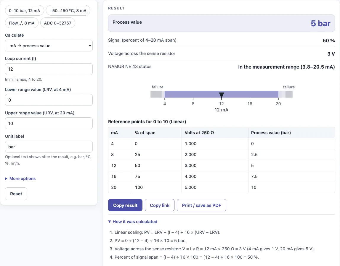
How to use the 4-20 mA calculator
- Choose a mode: mA → process value, process value → mA, or ADC counts → process value.
- Enter the range. LRV is the value at 4 mA and URV is the value at 20 mA. Add your unit label, such as bar or °C.
- For ADC counts mode, enter the counts at 4 mA and at 20 mA, for example 0 and 32767, or 6242 and 31208.
- Enter your input: the mA reading, the process value, or the counts.
- Pick Linear for most transmitters, or Square root for flow from a differential pressure transmitter.
- Check the sense resistor value. It defaults to 250 Ω, which gives 1–5 V.
- Read the results: process value, mA, percent of span, voltage, and NAMUR NE 43 status. The tool flags any signal at or below 3.6 mA or at or above 21.0 mA as a failure.
- Open How it was calculated to see the formula and each step with your numbers. The table of 4, 8, 12, 16 and 20 mA and the scale drawing update with your range.
Copy result copies the result lines with a link. Copy link copies the page address, which stores every input in the URL, so opening it later restores the same calculation. Print / save as PDF prints the inputs, results, calculation steps and the date.
How do you convert 4-20 mA to a process value?
Use the linear formula: PV = LRV + (I − 4) ÷ 16 × (URV − LRV), where I is the measured current. Subtract 4 mA, divide by the 16 mA span, then multiply by the engineering range. For 12 mA on a 0–10 bar range, (12 − 4) ÷ 16 = 0.5, so the pressure is 5 bar.
What is the 4-20 mA formula?
The linear formula is PV = LRV + (I − 4) ÷ 16 × (URV − LRV). The reverse is I = 4 + 16 × (PV − LRV) ÷ (URV − LRV), and percent of span is (I − 4) ÷ 16 × 100. For flow from a differential pressure transmitter, use the square-root form, PV = LRV + span × √((I − 4) ÷ 16). At 8 mA on a 0–100 m³/h range, √0.25 = 0.5, so the flow is 50 m³/h.
Why does 4-20 mA start at 4 mA?
4 mA is the live zero. A signal of 4 mA means the transmitter is working and the value is at the bottom of its range. A reading of 0 mA means the loop is broken, such as a cut wire or a power failure, so the controller can tell a fault from a low reading.
How do you convert 4-20 mA to 1-5 V?
Current becomes voltage across a resistor using Ohm’s law, V = I × R. With a 250 Ω sense resistor, 4 mA gives 0.004 × 250 = 1 V and 20 mA gives 0.020 × 250 = 5 V. Any mA value between them maps linearly to a voltage between 1 and 5 V.
What does NAMUR NE 43 mean?
NAMUR NE 43 is a recommendation for how transmitters report failures. Valid measurements fall within 3.8 to 20.5 mA. A signal at or below about 3.6 mA or at or above about 21 mA indicates a fault (the exact failure current is set in each transmitter), so the controller can separate a real fault from a valid reading near the ends of the range.
How do you scale 4-20 mA in a PLC?
A PLC analog input usually reports a raw count, not milliamps. Find the counts at 4 mA and at 20 mA from your module’s documentation, then apply the same linear formula with those counts in place of the 4 and 20 mA values. In ADC counts mode, enter those two count values, such as 0 and 32767, and the tool converts any count into a process value.
Sources
Checked October 2026:
- Wikipedia, Current loop for the 4 mA live zero and the 3.8 / 20.5 mA NAMUR NE 43 measuring range
- ICS Schneider on NAMUR NE 43 fault signals: failure at about 3.6 mA or below and about 21 mA or above, set per transmitter
- Linear scaling over the 16 mA span and square-root extraction for differential-pressure flow (flow ∝ √ΔP) are derivations; 1–5 V from 250 Ω by Ohm’s law
For estimation; verify critical designs against the applicable standard.
Worked examples
| Input | Result |
|---|---|
| 12 mA on a 0–10 bar range (Linear) | 5 bar |
| 2.5 bar on a 0–10 bar range | 8 mA |
| 8 mA on a -50–150 °C range (Linear) | 0 °C |
| 8 mA on a 0–100 m³/h range (Square root (flow from differential pressure)) | 50 m³/h |
| 16384 counts, 0 at 4 mA and 32767 at 20 mA, range 0–100 % | 50.002 % (12 mA) |
Calculated by the tool above with these values.
Frequently asked questions
Can I use the results in commercial work?
Yes. You can use the results in designs, quotes, documentation and reports without attribution.
Does the calculator work on a phone?
Yes. It runs in the browser, works on a phone, and uploads nothing.
How do I save a calculation to come back to later?
Click Copy link and save the address. The ?s= part of the link stores every input, so opening it restores the same calculation. For a dated printed record, use Print / save as PDF.
Why does 16384 counts give 50.002 %?
With 0 counts at 4 mA and 32767 counts at 20 mA, 16384 counts is 16384 ÷ 32767 = 0.50002 of the span, which is 50.002 %. That corresponds to 4 + 8.0003 = 12 mA.
What is 12 mA on a 4-20 mA loop?
12 mA is the middle of the range: 50 % of span. On a 0–10 bar transmitter it means 5 bar; on −50 to 150 °C it means 50 °C.
What voltage do I see across a 250 Ω resistor?
1 V at 4 mA and 5 V at 20 mA (V = I × R). Change the sense resistor in the tool to see other values.
Can I scale a reverse-acting range?
Yes. Enter the lower range value for 4 mA and the upper range value for 20 mA as your transmitter is configured; if the value at 4 mA is the larger one, the scaling simply runs downwards.
Related tools
- PLC simulator: test scaled analog inputs and outputs when you do not have hardware connected.
- PT100 table: look up resistance values when your temperature signal comes from an RTD.
- Thermocouple table: check millivolt readings against temperature for thermocouple inputs.
- Voltage divider calculator: size resistors when you need a voltage level other than the 1–5 V from a 250 Ω resistor.
- IP rating chart: choose enclosure protection for field-mounted transmitters.
- All calculators: browse the full set of tools on this site.