555 Timer Calculator
Enter R1, R2 and C to get the 555 astable frequency and duty cycle, or R and C for the monostable pulse width.
The 555 timer calculator works out the values for a 555 timer circuit: frequency and duty cycle in astable mode, or pulse time in monostable mode. Enter your resistors and capacitor, and the results update as you type. It covers five modes, so you can also solve backwards, finding the resistors for a target frequency or the capacitor for a set pulse time. It works with standard 555 chips such as the NE555 and LM555, and it runs in your browser. It is free, needs no sign-up, and works on a phone.
Use it for LED flashers, tone generators, clock signals and time delays.
How to use the 555 timer calculator
- Choose one of the five modes: astable frequency and duty cycle, astable resistors for a target frequency and duty, monostable pulse time, monostable resistor for a pulse time, or monostable capacitor for a pulse time.
- Enter the values you know for that mode. For astable frequency, that means R1, R2 and C. For a monostable pulse time, enter R and C.
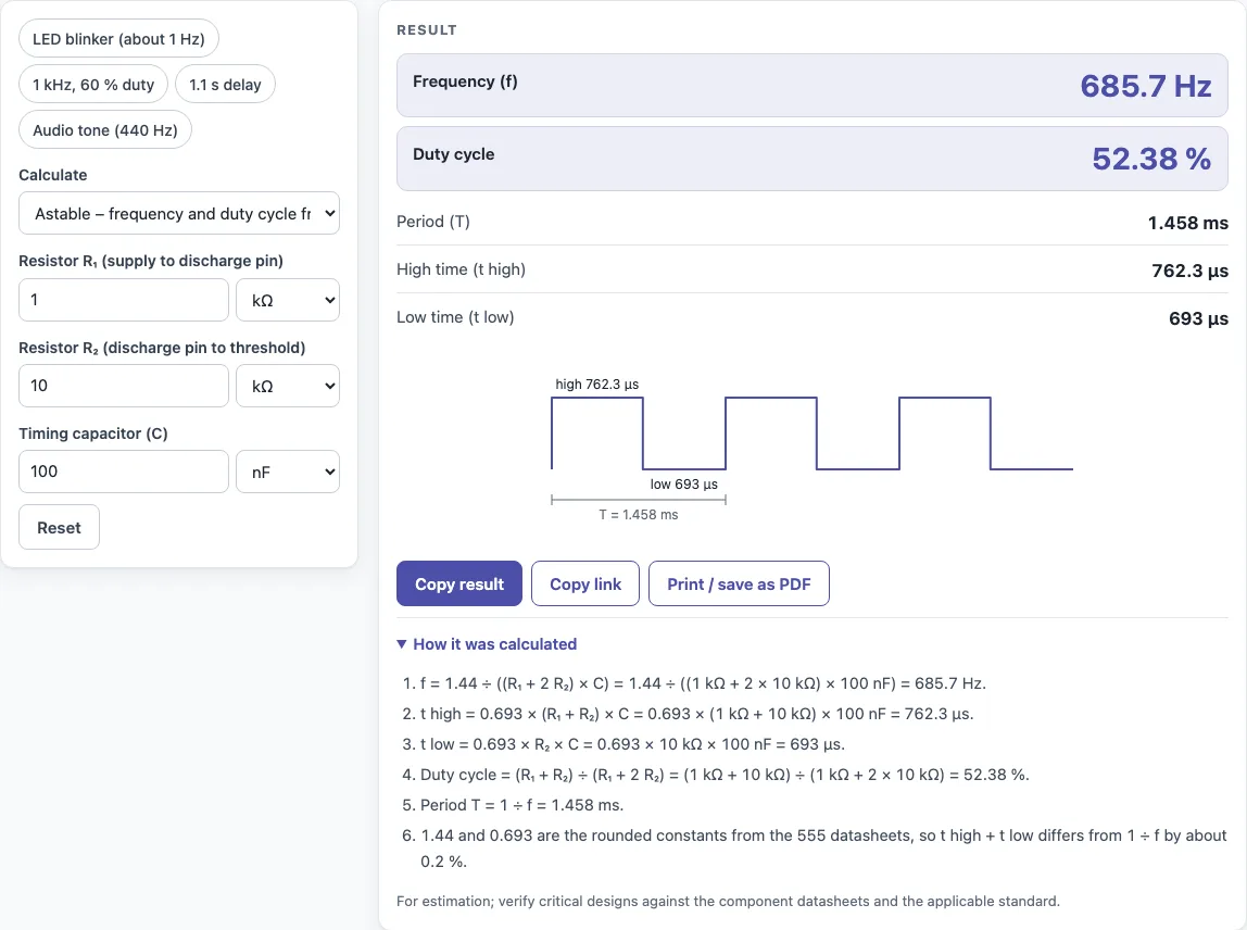
- Read the results. They update as you type, and the waveform drawing shows the high and low parts of the signal.
- Open “How it was calculated” to see the formula and each step with your own numbers. This is useful if you need to check the working.
- Check the duty cycle. In the basic astable circuit it is always above 50 %. For 50 % or less, the tool tells you to add a diode across R2.
- If you are solving for a part, change the mode and enter the values you already have, such as a target frequency and a capacitor.
Use Copy result to copy the result lines with a link back to the page. Copy link copies the page address, which stores every input, so opening it later restores the same calculation. Print / save as PDF prints the inputs, results, calculation steps and the date.
How do you calculate 555 timer frequency?
In astable mode, the frequency is f = 1.44 ÷ ((R1 + 2R2) × C). R1 and R2 are in ohms, C is in farads, and f comes out in hertz. The tool uses this formula and shows each step with your numbers.
For example, R1 = 1 kΩ, R2 = 10 kΩ and C = 100 nF give about 686 Hz.
What is the 555 astable formula?
An astable 555 switches on its own, with no trigger needed. The data-sheet formulas are:
- Frequency: f = 1.44 ÷ ((R1 + 2R2) × C)
- High time: 0.693 × (R1 + R2) × C
- Low time: 0.693 × R2 × C
- Duty cycle: (R1 + R2) ÷ (R1 + 2R2)
R1 runs from the supply to the discharge pin (7). R2 runs from the discharge pin to the threshold and trigger pins (6 and 2). C runs from there to ground. Because the constants are rounded, high time plus low time differs from 1 ÷ f by about 0.2 %.
How do you calculate the 555 monostable time?
In monostable mode, the 555 gives one output pulse each time it is triggered. The pulse length is t = 1.1 × R × C, with R in ohms, C in farads and t in seconds.
For example, R = 100 kΩ and C = 10 µF give t = 1.1 s. To go the other way, t = 500 ms with R = 47 kΩ needs C = 9.671 µF. The mode for solving the capacitor or resistor uses the same formula, rearranged.
How do I get 50 % duty cycle from a 555?
The basic astable circuit cannot reach 50 %. Its duty cycle is (R1 + R2) ÷ (R1 + 2R2), which is always above 50 %, because the charge path always includes R2 as well as R1.
To reach 50 % or less, place a diode across R2. The capacitor then charges through R1 alone, so the duty cycle becomes R1 ÷ (R1 + R2). A 50 % result therefore needs R1 equal to R2. Check the output on your circuit before you build it, because the tool’s duty figure applies to the basic circuit.
What resistor and capacitor for 1 Hz?
Start with a capacitor that is easy to find, such as 10 µF. Then the resistors must satisfy R1 + 2R2 ≈ 1.44 ÷ (1 × 10 µF) = 144 kΩ.
R1 = 47 kΩ and R2 = 47 kΩ give R1 + 2R2 = 141 kΩ, which is about 1.02 Hz. The duty cycle for these values is about 66.7 %. Enter them in the astable mode to confirm the result, or use the astable resistors mode with a target of 1 Hz to get values directly.
Sources
Checked October 2026:
- Texas Instruments NE555 data sheet (SLFS022): t = 1.1 R C (monostable), tH = 0.693 (RA + RB) C, tL = 0.693 RB C, f = 1.44 / ((RA + 2 RB) C)
For estimation; verify critical designs against the applicable standard.
Worked examples
| Input | Result |
|---|---|
| R₁ = 1 kΩ, R₂ = 10 kΩ, C = 100 nF | f = 685.7 Hz, duty 52.38 % |
| R₁ = 10 kΩ, R₂ = 10 kΩ, C = 10 µF | f = 4.8 Hz, duty 66.67 % |
| f = 1 kHz, duty 60 %, C = 100 nF | R₁ = 2.88 kΩ, R₂ = 5.76 kΩ |
| R = 100 kΩ, C = 10 µF | t = 1.1 s |
| t = 500 ms, R = 47 kΩ | C = 9.671 µF |
Calculated by the tool above with these values.
Frequently asked questions
Can the 555 timer calculator find the resistors for a target frequency?
Yes. The astable resistors mode takes a target frequency, a duty cycle and a capacitor, then returns R1 and R2. For example, 1 kHz at 60 % with 100 nF gives R1 = 2.88 kΩ and R2 = 5.76 kΩ.
What is the difference between astable and monostable mode?
Astable mode produces a continuous square-type signal that repeats on its own. Monostable mode produces one pulse of set length each time it is triggered. Pick the mode that matches what your circuit needs.
Why do high time and low time not exactly add up to 1 ÷ f?
The formulas use rounded constants, such as 0.693 and 1.44. This makes the sum of high time and low time differ from 1 ÷ f by about 0.2 %. The difference is small and does not change the design in most cases.
Does this work for NE555 and LM555 chips?
Yes. The formulas are the standard 555 data-sheet formulas, and the NE555 and LM555 both follow them. Check the datasheet for your exact chip if you need specific timing limits.
Can I use the results in commercial work?
Yes. Results may be used in commercial work, such as designs, quotes, documentation and reports, without attribution.
Related tools
- RC time constant calculator: use it to understand the RC timing that sets the monostable pulse length.
- LED resistor calculator: use it to size the current-limiting resistor for an LED driven by the 555 output.
- Resistor color code calculator: use it to read or check resistor values when you pick parts for the circuit.
- Capacitor series parallel calculator: use it to combine capacitors when a single value is not available.
- All calculators: use it to browse the full set of free tools on this site.