Audio Crossover Calculator
Enter the crossover frequency and the speaker impedances to get the capacitors and inductors for a 2-way passive crossover.
The audio crossover calculator works out the component values for a passive 2-way speaker crossover, the circuit that splits sound between a tweeter and a woofer. You choose a filter type, a crossover frequency, and the impedance of each driver, and the tool gives the capacitor and inductor values for both drivers, with a schematic. Results update as you type, so you can test different frequencies and filter types quickly. The tool runs in your browser, is free, needs no sign-up, and works on a phone.
It covers 1st-order and both common 2nd-order designs and suggests the nearest standard capacitor values.
How to use the Audio crossover calculator
- Choose the filter type: 1st order (6 dB per octave), 2nd order Butterworth (12 dB per octave), or 2nd order Linkwitz–Riley (12 dB per octave).
- Enter the crossover frequency.
- Enter the tweeter impedance and the woofer impedance in ohms. They can be different.
- Read the results. The tweeter gets a high-pass capacitor, and an inductor if you chose a 2nd order filter. The woofer gets a low-pass inductor, and a capacitor if you chose a 2nd order filter. Values are shown as the nearest E12/E24 standard values.
- Check the schematic to confirm how the parts connect.
- Open “How it was calculated” to see the formula and each step with your own numbers.
When you are happy with the result, use Copy result to copy the result lines with a link. Copy link copies the page address, which stores every input, so opening it later restores the same calculation. Print / save as PDF prints the inputs, results, calculation steps, and the date.
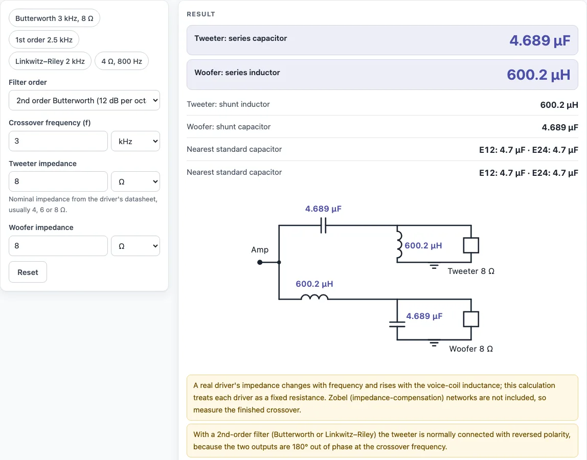
The presets show a Butterworth crossover at 3 kHz with 8 Ω drivers, a 1st-order crossover at 2.5 kHz, a Linkwitz–Riley at 2 kHz and a 4 Ω system at 800 Hz. The schematic under the result shows where each part goes: the capacitor in series with the tweeter and the inductor in series with the woofer, with the second-order parts across each driver.
How do you calculate a speaker crossover?
A speaker crossover is calculated by choosing a crossover frequency, a filter order, and the impedance of each driver, then putting those numbers into the formula for that filter. Each formula uses 2π f R, where f is the crossover frequency in hertz and R is the driver impedance in ohms, so the component values depend on both.
For a 1st order filter, the tweeter gets one capacitor, C = 1 ÷ (2π f R), and the woofer gets one inductor, L = R ÷ (2π f). The filter rolls off at 6 dB per octave. For example, at 2.5 kHz with 8 Ω drivers, the tweeter capacitor is 7.96 µF and the woofer inductor is 509 µH.
Second order filters roll off at 12 dB per octave and use two parts per driver. The tweeter gets a capacitor and an inductor, and the woofer gets an inductor and a capacitor. The values also depend on the filter’s Q, which is why the Butterworth and Linkwitz–Riley formulas differ.
What is the difference between Butterworth and Linkwitz–Riley?
Both are second order filters with a slope of 12 dB per octave, but they use different Q values. Butterworth uses Q 0.707, and Linkwitz–Riley uses Q 0.5. The Q value changes the shape of the response around the crossover point, and it changes the component values.
The formulas show the difference. For Butterworth, the woofer inductor is L = R √2 ÷ (2π f). For Linkwitz–Riley, it is L = R ÷ (π f). At 3 kHz with 8 Ω drivers, Butterworth gives a tweeter capacitor of 4.69 µF and an inductor of 600 µH. At 2 kHz with a 6 Ω tweeter and an 8 Ω woofer, Linkwitz–Riley gives a tweeter capacitor of 6.63 µF and an inductor of 955 µH, and a woofer inductor of 1.27 mH and capacitor of 4.97 µF.
Run both filter types at the same frequency and impedances to compare the parts they require.
Sources
Checked October 2026:
- Wikipedia, Linkwitz–Riley filter for the alignments
- Second-order component values from the filter equations (Butterworth Q = 0.707: L = √2 R / (2πf), C = 1 / (2πf √2 R)); second-order low-pass and high-pass outputs are 180° apart at the crossover frequency, hence the reversed tweeter
- Values assume a resistive driver impedance; real drivers vary with frequency
For estimation; verify critical designs against the applicable standard.
Worked examples
| Input | Result |
|---|---|
| 2nd order Butterworth, f = 3 kHz, 8 Ω / 8 Ω | Tweeter C = 4.689 µF, L = 600.2 µH; woofer L = 600.2 µH, C = 4.689 µF |
| 1st order, f = 2.5 kHz, 8 Ω / 8 Ω | Tweeter C = 7.958 µF; woofer L = 509.3 µH |
| 2nd order Linkwitz–Riley, f = 2 kHz, 6 Ω / 8 Ω | Tweeter C = 6.631 µF, L = 954.9 µH; woofer L = 1.273 mH, C = 4.974 µF |
| 2nd order Butterworth, f = 800 Hz, 4 Ω / 4 Ω | Tweeter C = 35.17 µF, L = 1.125 mH; woofer L = 1.125 mH, C = 35.17 µF |
Calculated by the tool above with these values.
Frequently asked questions
What capacitor for a tweeter crossover?
The tool shows the tweeter capacitor value, rounded to the nearest standard E12 or E24 value, under the results. Use a capacitor with a voltage rating well above the power the tweeter will receive. Choose a non-polarized type, because electrolytic capacitors are not suitable for crossover networks.
What crossover frequency should I use?
Pick a frequency where both drivers can reproduce sound well, which usually means one that sits above the woofer’s resonance and within the tweeter’s safe operating range. The manufacturer’s data sheets for your drivers are the best guide to these limits. Try a few frequencies in the tool and compare the component values before you choose.
Why reverse the tweeter polarity?
With 2nd order filters, the tweeter is normally connected with reversed polarity. This is because a second order high-pass filter shifts the phase of the tweeter’s signal relative to the woofer’s, and reversing the tweeter helps the two outputs line up near the crossover point. Check the schematic for the connections to use.
Can I use different impedances for the tweeter and woofer?
Yes. The tweeter and woofer impedances are entered separately, and each driver’s values are calculated from its own impedance. For example, a 6 Ω tweeter with an 8 Ω woofer gives different results for each driver.
Why do my measured results differ from the calculated values?
The formulas assume a constant, resistive driver impedance. Real drivers’ impedance changes with frequency, and impedance compensation such as a Zobel network is not included in the tool. Measure the finished crossover and adjust the component values.
Can I use the results in commercial work?
Yes. Results may be used in commercial work, including designs, quotes, documentation, and reports, without attribution.
Related tools
- Low pass filter calculator: use it when you need to work out a low-pass filter on its own, outside a full speaker crossover.
- Reactance calculator: use it to find the reactance of a capacitor or inductor at a given frequency.
- Inductance calculator: use it to check or work out inductor values for your crossover.
- Decibel calculator: use it to convert between decibel values and ratios when comparing filter slopes or levels.
- Capacitor series parallel calculator: use it to combine standard capacitors when no single value matches your result.
- All calculators: use it to browse every calculator on this site.