Low Pass Filter Calculator
Enter the components to get the cutoff frequency, or a target frequency to get the component, with the response drawn on a Bode plot.
The low pass filter calculator finds the cutoff frequency of an RC, RL or LC low pass filter from your component values, and it can work backwards to give the R, C or L you need for a target cutoff. It runs in your browser, is free, and needs no sign-up. You can use it as an RC low pass calculator, an RL or LC filter calculator, or an LPF calculator for quick design checks.
The tool also shows how the filter responds at a chosen frequency, so you can see the gain and phase before you build anything. Whether you are a student checking homework, a hobbyist planning a circuit, or an engineer writing up a design, the same steps apply. Results are yours to use in commercial work without attribution.
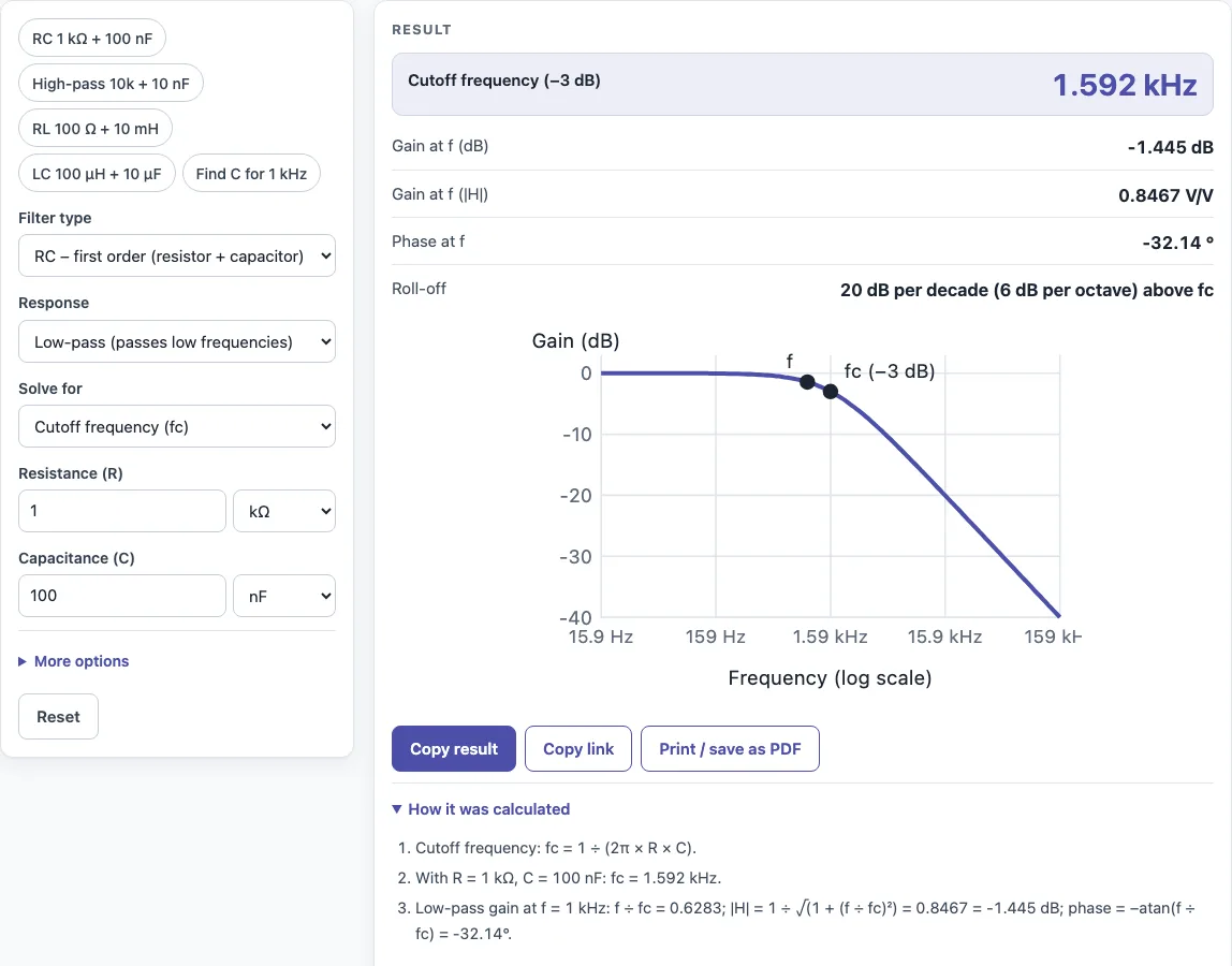
How to use the low pass filter calculator
- Choose the filter type: RC, RL or LC.
- Select low-pass. The cutoff formulas are the same for high-pass, but the response is reversed.
- To find the cutoff frequency, enter your component values, such as R and C for an RC filter, or L and C for an LC filter.
- To find a component value instead, choose the option to solve for R, C or L, then enter your target cutoff frequency and the component you already have.
- Read the cutoff frequency in the results. Results update as you type, so you can adjust a value and watch the change.
- If you want the response at a specific frequency, enter it. The gain appears in V/V and dB, along with the phase. A Bode magnitude plot on a log axis is also drawn.
- Open “How it was calculated” to see the formula and each step with your numbers.
Copy result copies the result lines with a link. Copy link copies the page address, which stores every input, so opening it later restores the same calculation. Print / save as PDF prints the inputs, results, calculation steps and the date, which is useful for reports.
How do you calculate the cutoff frequency of a low pass filter?
For a first-order RC low pass filter, the cutoff frequency is fc = 1 ÷ (2π R C), with R in ohms and C in farads. Signals well below fc pass through almost unchanged, and signals above fc are increasingly attenuated.
Take R = 1 kΩ and C = 100 nF. Convert 100 nF to 0.0000001 F, multiply 2π × 1000 × 0.0000001 to get 0.000628, then divide 1 by that. The result is about 1,592 Hz, or 1.592 kHz.
The gain at any frequency f is |H| = 1 ÷ √(1 + (f ÷ fc)²). At 1 kHz, that is 1 ÷ √(1 + (1000 ÷ 1592)²), which is about 0.848 V/V, or −1.45 dB. Below fc the gain stays close to 1, and it falls off past fc. The calculator performs these steps for you and shows each one.
What is the RC low pass filter formula?
The RC low pass formula is fc = 1 ÷ (2π R C). The phase shift at frequency f is −atan(f ÷ fc), so the output lags the input more as frequency rises. Above fc, a first-order filter rolls off at 20 dB per decade, which is 6 dB per octave.
The same idea applies to other first-order filters. An RL filter uses fc = R ÷ (2π L). A second-order LC filter uses f0 = 1 ÷ (2π √(L C)) and has a characteristic impedance of Z0 = √(L ÷ C). For a 100 µH inductor and 10 µF capacitor, f0 is about 5.03 kHz.
How do I choose R and C for a low pass filter?
Pick one component, then solve for the other with the target cutoff: C = 1 ÷ (2π R fc). For a 1 kHz filter with R = 10 kΩ, C = 15.92 nF; the nearest standard 15 nF gives about 1.06 kHz. This low pass filter calc does the same in ‘Solve for’ mode, and the LP filter calculator gain line shows the attenuation at any frequency you check.
Sources
Checked October 2026:
- Wikipedia, RC circuit: fc = 1 / (2πRC), τ = RC
- RL fc = R / (2πL) and LC f0 = 1 / (2π√(LC)) from the same first- and second-order circuit equations (Horowitz and Hill, The Art of Electronics)
For estimation; verify critical designs against the applicable standard.
Worked examples
| Input | Result |
|---|---|
| R = 1 kΩ, C = 100 nF | fc = 1.592 kHz, -1.445 dB at 1 kHz |
| R = 10 kΩ, C = 10 nF | fc = 1.592 kHz, -10.47 dB at 500 Hz |
| R = 100 Ω, L = 10 mH | fc = 1.592 kHz, -16.07 dB at 10 kHz |
| L = 100 µH, C = 10 µF | fc = 5.033 kHz |
| R = 10 kΩ, fc = 1 kHz | C = 15.92 nF, -3.01 dB at 1 kHz |
Calculated by the tool above with these values.
Frequently asked questions
How do I choose R and C for a low pass filter?
Pick your target cutoff frequency, then choose a convenient standard value for C. Calculate R = 1 ÷ (2π fc C), then round to the nearest standard resistor value. Enter the rounded values into the calculator to confirm the new cutoff.
What does −3 dB mean at the cutoff frequency?
At fc, the output has dropped to about 0.707 of the input amplitude. In dB, that is −3.01 dB. It is the point where the filter has begun to clearly attenuate the signal, and it is the usual definition of the cutoff.
What is the difference between a low pass and a high pass filter?
A low pass filter passes frequencies below its cutoff and attenuates those above it. A high pass filter does the reverse. Both use the same cutoff formulas, so the calculator gives the same cutoff value for either type.
Why does the LC filter result depend on the source and load?
The LC option gives only f0 and Z0. The real response depends on the impedance of the source driving the filter and the load it feeds, so check those values in your circuit before relying on the result.
Can I use the results in commercial work?
Yes. You can use results in designs, quotes, documentation and reports without attribution.
Does the calculator work on a phone?
Yes. It runs entirely in your browser and works on a phone. Nothing is uploaded.
Related tools
- RC time constant calculator: use it to find the time constant of an RC circuit, which is closely linked to its filter behaviour.
- Reactance calculator: use it to find the capacitive or inductive reactance of a component at a given frequency.
- Audio crossover calculator: use it to design crossover networks that split audio signals between speakers.
- Op amp gain calculator: use it to work out the gain of an op amp stage, which you may combine with a filter.
- Decibel calculator: use it to convert between dB values and linear ratios when reading filter gain.
- All calculators: browse the full set of tools on this site.