PCB Trace Width Calculator
Enter the current, copper weight and allowed temperature rise to get the minimum trace width, with resistance and loss for a length.
The PCB trace width calculator gives the minimum width a copper trace needs to carry a given current within a chosen temperature rise. You enter the current, temperature rise, copper weight and layer, and it returns the width in millimetres and mil. It runs in your browser, is free, and needs no sign-up. It also shows copper thickness and cross-section, and if you add a trace length, it reports resistance, voltage drop and power loss. Use it as a PCB trace size calculator for power, ground and other high-current traces. It works on a phone.
It is a circuit board trace width calculator and a quick PCB trace width calc in one.
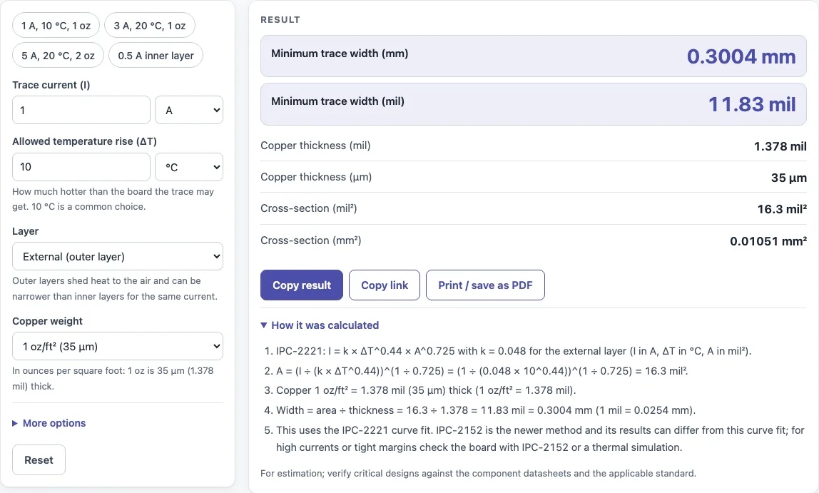
How to use the PCB trace width calculator
- Enter the current. You can type amps or milliamps, such as 500 mA.
- Enter the allowed temperature rise. You can use °C or °F.
- Choose the copper weight: 0.5, 1, 2 or 3 oz/ft².
- Choose External (outer layer) or Internal (inner layer) for where the trace sits.
- Optional: enter a trace length and an ambient temperature to get resistance, voltage drop and power loss.
- Read the minimum width in mm and mil, along with copper thickness and cross-section in mil² and mm². The results update as you type.
- Open “How it was calculated” to see the formula with your own numbers in each step.
Copy result copies the result lines with a link back to the calculation. Copy link copies the page address, which stores every input in the URL (?s=…), so opening it later restores the same calculation. Print / save as PDF prints the inputs, results, calculation steps and the date.
The presets show 1 A at a 10 °C rise on 1 oz copper, 3 A at 20 °C, 5 A on 2 oz copper and 0.5 A on an inner layer. Enter the optional trace length and ambient temperature to see the resistance, voltage drop and power loss of the trace, which matter for long power runs and current-sense paths.
How wide should a PCB trace be for 1 amp?
For 1 A on a 1 oz/ft² outer layer with a 10 °C temperature rise, the minimum width is about 0.30 mm (11.8 mil). The calculator gives 0.3004 mm (11.83 mil) for these settings, and the answer changes with copper weight, layer and allowed rise.
Three things set the width. Higher current needs a wider trace. A smaller allowed temperature rise needs a wider trace, because the trace must shed less heat per unit of current. Thicker copper gives more cross-section at the same width, so a 2 oz/ft² trace can be narrower than a 1 oz/ft² trace for the same current. For example, 3 A at a 20 °C rise on 1 oz copper needs about 0.90 mm (35.3 mil).
Inner layers need more width. They shed heat less easily than outer layers, so inner-layer traces need about 2.6 times the cross-section of outer-layer traces for the same current and temperature rise.
What is the IPC-2221 trace width formula?
The calculator uses the IPC-2221 curve fit: I = k × ΔT^0.44 × A^0.725. Here I is current in amps, ΔT is temperature rise in °C, A is cross-section in mil², and k is 0.048 for external layers or 0.024 for internal layers.
To find the width, the calculator solves the formula for A: A = (I ÷ (k × ΔT^0.44))^(1/0.725). It then divides A by the copper thickness to get the width. One oz/ft² copper is 1.378 mil (35 µm) thick. For 1 A, a 10 °C rise and an outer layer, 10^0.44 is about 2.75, which gives A of about 16.3 mil². Dividing by 1.378 gives about 11.8 mil.
IPC-2152 is a newer method based on more test data. This calculator uses the IPC-2221 curve fit and says so on the page.
Sources
Checked October 2026:
- IPC-2221 curve fit I = k ΔT^0.44 A^0.725 with k = 0.048 (external) and 0.024 (internal), as published by Digi-Key and NextPCB; 1 oz copper = 1.378 mil
- NBS Circular 31 for the resistivity of annealed copper
- The IPC-2221 curves ignore copper pours, vias and airflow; check against IPC-2152 or your board maker for critical traces
For estimation; verify critical designs against the applicable standard.
Worked examples
| Input | Result |
|---|---|
| 1 A, ΔT 10 °C, 1 oz/ft², External (outer layer) | 0.3004 mm (11.83 mil) |
| 3 A, ΔT 20 °C, 1 oz/ft², External (outer layer) | 0.8976 mm (35.34 mil) |
| 5 A, ΔT 20 °C, 2 oz/ft², External (outer layer) | 0.9079 mm (35.74 mil) |
| 500 mA, ΔT 10 °C, 1 oz/ft², Internal (inner layer) | 0.3004 mm (11.83 mil) |
| 2 A, ΔT 36 °F, 0.5 oz/ft², External (outer layer) | 1.026 mm (40.4 mil) |
Calculated by the tool above with these values.
Frequently asked questions
How does copper weight affect trace width?
Copper weight sets the thickness of the trace. A thicker trace has more cross-section at the same width, so it can carry more current or run at a lower temperature rise. To keep the same current, a thicker copper layer allows a narrower trace.
Why do inner layer traces need to be wider?
Inner layers are buried between other layers and release heat less easily than outer layers. The calculator halves k for internal layers, which makes the required cross-section about 2.6 times larger for the same current and rise.
How much current can a PCB trace carry?
There is no single fixed number. A given width carries different currents depending on copper weight, layer and allowed temperature rise. Enter your planned current to find the minimum width for your settings.
Does this calculator show trace impedance?
No. It sizes a trace for current and temperature rise, and reports resistance, voltage drop and power loss when you add a length. For impedance, you need a separate tool.
Can I use the results in commercial work?
Yes. You can use results in designs, quotes, documentation and reports without attribution.
Is IPC-2221 the right standard for my board?
IPC-2221 is the method this calculator uses. If you need the newer IPC-2152 approach, which is based on more test data, check that method separately before finalising a design.
Related tools
- LED resistor calculator: use it to find the series resistor value for an LED.
- Parallel resistor calculator: use it to combine resistors in parallel and find the equivalent value.
- Voltage divider calculator: use it to find the output voltage or resistor values of a divider.
- Capacitor series parallel calculator: use it to combine capacitors in series or parallel.
- Wavelength calculator: use it to convert between wavelength and frequency.
- All calculators: browse the full set of free calculators on the site.