PLC Simulator (Ladder Logic)
Write or pick a ladder program, switch the inputs and watch the rungs energise, timers run and outputs change, all in your browser.
This PLC simulator is a free, browser-based ladder logic simulator for learning how programmable logic controllers work. You write a program as one rung per line in Rockwell-style mnemonics, switch the inputs on and off, and watch power flow through the ladder diagram. It needs no download and no sign-up, and nothing you enter is uploaded.
Use it to practise ladder programming, test a start/stop motor circuit, or check how timers and counters behave before you work on real equipment. Each scan reads inputs I1 to I8, evaluates the rungs from top to bottom and updates outputs Q1 to Q8, just as a real PLC does.
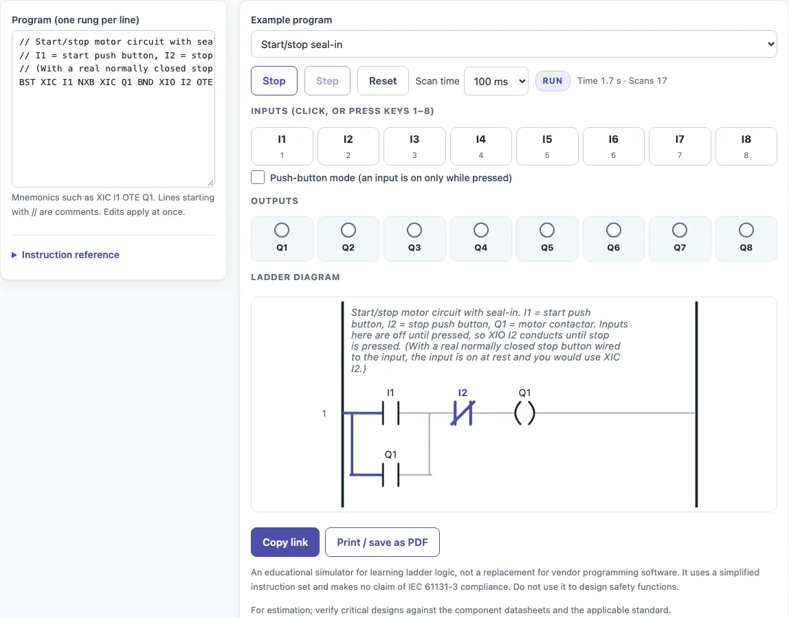
How to use the PLC simulator
- Type your program into the editor, one rung per line. Start a line with // to add a comment. Or load a built-in example: start/stop seal-in, set/reset, on-delay timer, counter with reset, traffic light, or alternating pumps.
- Set the scan time between 50 and 500 ms.
- Press Run to start scanning. Press Stop to halt, Step to run a single scan, and Reset to clear the program state.
- Click the input buttons I1 to I8, or press keys 1 to 8. For a momentary button, turn on push-button mode so an input is on only while it is pressed.
- Watch the power flow through each rung and the output lamps Q1 to Q8.
- Check the memory bits and the timer and counter values shown on the page. If a line contains an error, the message names that line, and that rung is not run. Warnings flag double coils and rungs without an output.
Copy link saves the program and inputs in the page address (?s=), so you can share it or reopen it later. Print / save as PDF prints the program listing, the I/O states, the timers and counters, and the date.
The instruction reference on the page lists every mnemonic and address.
What is a PLC simulator?
A PLC (programmable logic controller) is an industrial computer. It reads switches and sensors, runs a program, and drives outputs such as motors and lamps. A PLC simulator copies that behaviour on screen, so you can test logic without any machine.
This tool follows the same scan cycle as a real controller. Each scan reads the inputs, evaluates the rungs from top to bottom, and writes the outputs. The scan time you set controls how often this loop repeats, which decides how quickly outputs react to input changes.
How do you write ladder logic?
Ladder logic looks like an electrical diagram. The left rail is power, and each rung is a set of conditions that, when met, energises an output at the right end.
XIC (examine if closed) is a normally open contact. It passes power when its bit is 1. XIO (examine if open) is a normally closed contact. It passes power when its bit is 0. Contacts placed in series on one rung act as an AND, so every condition must be true.
Parallel legs act as an OR. Start a branch with BST, add a leg with NXB, and close it with BND. Branches can be nested. OTE energises an output while its rung is true. OTL latches an output on, and OTU unlatches it. Timers (TON, TOF), counters (CTU) and resets (RES) complete the instruction set.
The ladder diagram is redrawn from the text on every change and highlights the energised contacts and coils, so you can see which condition is blocking a rung.
Sources
Checked October 2026:
- Instruction behaviour (XIC, XIO, OTE, OTL, OTU, TON, TOF, CTU, RES and the .EN / .TT / .DN bits) follows the common ladder-logic conventions, simplified for teaching; it is not vendor software
- Allen-Bradley and Rockwell Automation are trademarks of Rockwell Automation; this site is not affiliated
For estimation; verify critical designs against the applicable standard.
Worked examples
| Input | Result |
|---|---|
| Start/stop seal-in; inputs: I1 200; - 500; I2 200 | Outputs ON: none (after 900 ms) |
| On-delay timer; inputs: I1 3000 | Outputs ON: Q2 (after 3,000 ms) |
| Counter with reset; inputs: I1 100; - 100; I1 100; - 100; I1 100; - 100 | Outputs ON: Q1 (after 600 ms) |
| Traffic light; inputs: I1 6500 | Outputs ON: Q1 (after 6,500 ms) |
| Alternating pumps; inputs: I1 300; - 300; I1 300 | Outputs ON: Q2 (after 900 ms) |
Calculated by the tool above with these values.
Frequently asked questions
Is this PLC simulator free?
Yes. It is free to use, needs no download and no sign-up, and nothing is uploaded. It is a simplified teaching simulator, not vendor programming software, and it does not claim IEC 61131-3 compliance.
What is a seal-in (latching) circuit?
A seal-in circuit keeps an output on after the button that started it is released. In this tool, the rung BST XIC I1 NXB XIC Q1 BND XIO I2 OTE Q1 does this. Pressing I1 turns Q1 on, and the parallel XIC Q1 branch holds it on. Pressing I2 breaks the hold because XIO I2 conducts only while I2 is off.
What is the difference between XIC and XIO?
XIC (examine if closed) is a normally open contact that passes power when its bit is 1. XIO (examine if open) is a normally closed contact that passes power when its bit is 0. If a stop button is wired normally closed, its input is on at rest, so you would use XIC for it instead of XIO.
How does a TON timer work?
TON is an on-delay timer. Its preset can be given in milliseconds or written like 2s. Its output turns on only after the input has stayed on for the full preset time. Its bits are .DN (done), .TT (timing) and .EN (enabled). In the built-in on-delay timer example (preset 2 s), T1.TT lights Q1 while the timer runs and Q2 turns on once I1 has been on for 2 seconds.
How does a PLC scan cycle work?
Each scan reads the input states, evaluates every rung from top to bottom using those inputs and the current memory and timer values, and then writes the results to the outputs. The cycle then repeats continuously. In this tool, the scan time you choose sets how long each cycle takes, from 50 to 500 ms.
Related tools
- 4-20 mA calculator: use it to convert a process value to and from a 4-20 mA loop signal.
- Motor torque calculator: use it when you need to estimate the torque a motor produces.
- Synchronous speed calculator: use it to find the synchronous speed of an AC motor from its supply frequency and pole count.
- IP rating chart: use it to look up the ingress protection rating of an enclosure.
- NEMA enclosure rating chart: use it to compare NEMA enclosure types for a panel or cabinet.
- All calculators: use it to browse every calculator on this site.