Reactance Calculator (Inductive Reactance Formula)
Get the reactance of an inductor or capacitor at a frequency, or the impedance, phase and resonance of a series RLC circuit.
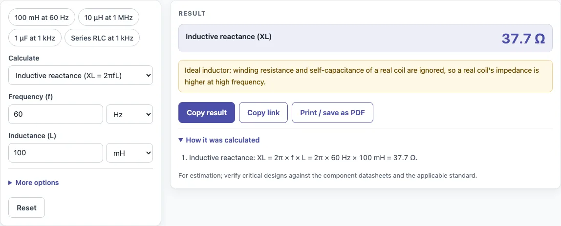
How to use the Reactance calculator
- Enter the frequency. You can type Hz, kHz or MHz, for example 60 Hz, 1 kHz or 1 MHz.
- Enter the inductance in nH, µH, mH or H, for example 100 mH. This gives you XL.
- Enter the capacitance in pF, nF or µF, for example 1 µF. This gives you XC.
- For a series RLC circuit, also enter the resistance in ohms. Leave it out if you only need reactance.
- Read the results. XL and XC appear in ohms. With R, L and C filled in, you also see impedance Z, phase angle φ, power factor cos φ, whether the circuit is inductive or capacitive, and resonant frequency f₀.
- If you enter an applied voltage, the result also includes the current, I = V ÷ Z.
- Open “How it was calculated” to see the formula and each step with your numbers.
Copy result copies the result lines with a link. Copy link copies the page address, which stores every input, so opening it later restores the same calculation. Print / save as PDF prints the inputs, results, calculation steps and the date, which is useful for a record of your work.
The presets show 100 mH at 60 Hz, 10 µH at 1 MHz, 1 µF at 1 kHz and a series RLC circuit at 1 kHz.
What is the inductive reactance formula?
Inductive reactance is the opposition an inductor offers to alternating current. It is measured in ohms and calculated with XL = 2π f L, where f is frequency in hertz and L is inductance in henries.
Because frequency multiplies the formula, inductive reactance rises as frequency rises. Convert the inductance to henries first. For 100 mH at 60 Hz, L = 0.1 H, so XL = 2π × 60 × 0.1 = 37.7 Ω. For 10 µH at 1 MHz, L = 0.00001 H, so XL = 2π × 1,000,000 × 0.00001 = 62.8 Ω.
Inductive reactance does not dissipate power the way resistance does. It stores energy in the magnetic field and returns it to the circuit each cycle. That is why it is called reactance rather than resistance.
What is the capacitive reactance formula?
Capacitive reactance is the opposition a capacitor offers to alternating current. It is also measured in ohms and calculated with XC = 1 ÷ (2π f C), where C is capacitance in farads.
Frequency sits in the denominator, so capacitive reactance falls as frequency rises. This is the opposite trend to inductive reactance. For 1 µF at 1 kHz, C = 0.000001 F, so XC = 1 ÷ (2π × 1000 × 0.000001) = 159.2 Ω. For 10 µF at 50 Hz, XC = 1 ÷ (2π × 50 × 0.00001) = 318.3 Ω.
Because the two reactances move in opposite directions, a circuit containing both can have them cancel. The net reactance is X = XL − XC. When XL is larger, X is positive and the circuit behaves as inductive. When XC is larger, X is negative and the circuit behaves as capacitive.
What happens at resonance?
At f0 = 1 ÷ (2π √(LC)) the inductive and capacitive reactances are equal and cancel, so a series RLC circuit’s impedance falls to R alone and the current is largest. For 10 mH and 1 µF, f0 = 1.592 kHz.
Sources
Checked October 2026:
- Wikipedia, Electrical reactance: XL = 2πfL, XC = 1 / (2πfC)
- Resonance f0 = 1 / (2π√(LC)) where XL = XC (derived)
For estimation; verify critical designs against the applicable standard.
Worked examples
| Input | Result |
|---|---|
| f = 60 Hz, L = 100 mH | XL = 37.7 Ω |
| f = 1 MHz, L = 10 µH | XL = 62.83 Ω |
| f = 1 kHz, C = 1 µF | XC = 159.2 Ω |
| f = 50 Hz, C = 10 µF | XC = 318.3 Ω |
| f = 1 kHz, R = 50 Ω, L = 10 mH, C = 1 µF | Z = 108.5 Ω, φ = -62.57°, f₀ = 1.592 kHz |
Calculated by the tool above with these values.
Frequently asked questions
What is the impedance of an inductor?
For an ideal inductor with no resistance, the impedance equals its inductive reactance, so Z = XL = 2π f L, in ohms. A real inductor also has some winding resistance, which adds to its total impedance.
How do you calculate the impedance of an RLC circuit?
Find XL and XC, subtract them to get X = XL − XC, then use Z = √(R² + X²). With R = 50 Ω, L = 10 mH and C = 1 µF at 1 kHz, XL is 62.8 Ω and XC is 159.2 Ω, so X = −96.3 Ω and Z = 108.5 Ω.
What happens at resonance?
At resonance, XL equals XC, so X = 0 and the two reactances cancel. The impedance then equals the resistance alone, Z = R, and the phase angle is zero. The resonant frequency is f₀ = 1 ÷ (2π √(LC)); for 10 mH and 1 µF, it is 1.592 kHz.
Can I use the results in commercial work?
Yes. Results may be used in designs, quotes, documentation and reports without attribution.
Do I need to sign up or install anything?
No. The calculator is free, needs no sign-up, and runs entirely in your browser. Nothing you enter is uploaded, and it works on a phone.
Is reactance the same as impedance?
No. Reactance is the imaginary part; impedance combines it with resistance: Z = √(R² + X²).
Related tools
- Inductance calculator: use it when you need to find the inductance of a coil before calculating its reactance.
- Low pass filter calculator: use it to find the cutoff frequency of a filter built from resistors and capacitors or inductors.
- RC time constant calculator: use it to find how quickly a resistor and capacitor charge or discharge.
- Capacitor series parallel calculator: use it to find the combined capacitance before calculating capacitive reactance.
- Wavelength calculator: use it to convert between frequency and wavelength for radio and signal work.
- All calculators: use it to browse every calculator on the site.